Giacomo, JFETs microphone preamplifier
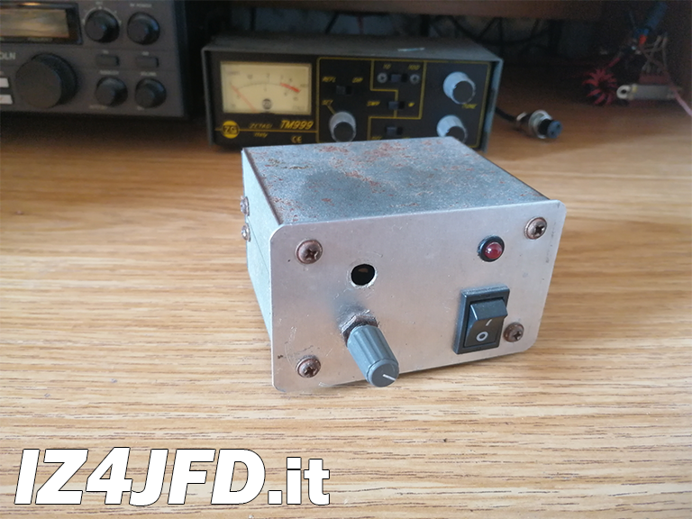
Giacomo is the first microphone preamplifier I built myself, to use it with my Kenwood TS-140S. It is composed of a preamplifier stage featuring 3 field effect transistors (JFETs), and a power supply stage. Technically, Giacomo is very similar to other models from well-known brands in the amateur radio market. It was not my intention to invent a microphone that could worthily replace what is already available. I never thought about it and, if I had, I don't think I would have succeeded. I just liked how it works, and I still do. The positive feedback I got from amateur radio fellows who listened to it was the evidence that led me to believe in the usefulness of this project.
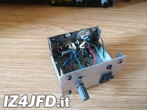
Preamplifier stage
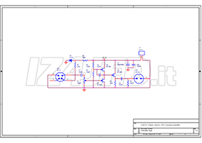
-

Giacomo - Preamplifier stage
Schematic diagram (PDF)
Giacomo's preamplifier is a simple circuit in which there are 3 field effect transistors (JFETs), in addition to the components (resistors, capacitors, etc.) necessary to bias these semiconductors, to couple the preamplifier to the microphone capsule and to the RTX's microphone input, and to supply power to an ECM cartridge eventually connected to Giacomo's input. After passing through the high pass filter composed by C1 and R1 (whose cut-off frequency is approximately 15 Hz), the AF signal reaches the first two JFETs, a pair of BF245C included in a circuit called "microamp" (μ- amp, or microbooster), capable of amplifying up to 500 times any signal placed at its input.
Commonly used in the tubes age, the microamp was applied to semiconductors by National Semiconductors, which - in its AN32 application note - includes some schemes featuring JFETs in μ-amp configuration. A few years later, Jack Orman, a guitarist and audio effects experimenter, published the scheme of a circuit based on the μ-amp, which he called “microbooster”.[1]
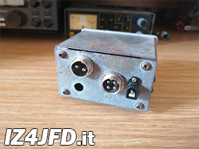
The amplified AF signal is taken from the output of the microamp and applied to the gate of the third transistor, a BF245B, which is DC coupled (i.e., without decoupling capacitor) to the previous stage and is used in a common drain configuration, from whose source the AF signal is taken and continues towards the RTX. The particular configuration of the third FET allows a low impedance output which, in my intentions, should allow the use of (almost) any audio frequency signal cable to connect the preamp to the RTX. All this to avoid any negative effect (attenuation) on the signal itself (in particular, on its highest frequencies) which could be caused by using a low impedance cable on high impedance output (such as the drain of a FET). In addition to this AF circuit, the preamplifier also houses the components that allow to supply power to an ECM cartridge. That is, a ZTE2 zener diode, with its current limiting resistor, which produces 2 Vdc that go to the cartridge. This voltage is available on pin 2 of Giacomo's AF input connector. Between the anode of the zener (which operates in direct polarization) and Giacomo's input, there is the load resistor for the JFET integrated inside the ECM cartridge: downstream of this resistance (following the path of the DC power going to the transducer) is the point where the audio signal, arriving from the cartridge, is picked up and sent to the microamp input. Everything is housed inside a small metal box, isolated from the DC ground of the preamplifier and its power supply, but connected to the copper braid of the cables placed at the input and output of Giacomo, allowing the necessary electrical continuity for the shielding conductor from the microphone cartridge to the microphone input of the RTX.
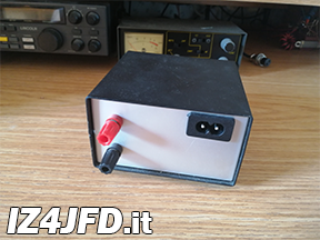
Power supply stage
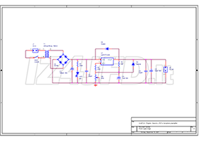
-

Giacomo - Power supply stage
Schematic diagram (PDF)
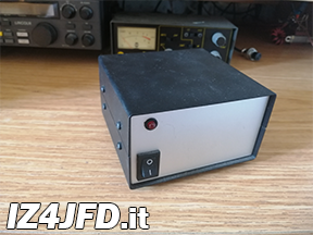
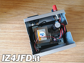
Giacomo's power supply is based on an LM317, the integrated circuit that regulates the voltage applied to the preamplifier. The circuit starts with a transformer (a 4VA one), whose primary accepts the mains voltage (230Vac, 50Hz), while the secondary produces 35Vac and a 100mA max. current. Once rectified and filtered, the DC voltage is regulated by the LM317, which supplies 40Vdc as this supply stage's output. These 40Vdc are equally divided between the two transistors of the microamp circuit (i.e., each transistor is supplied with 20Vdc). 20Vdc is also the voltage on the gate of the third JFET, coupled directly to the output of the microamp. To correctly bias Giacomo's output transistor, it is necessary that on its source be present a DC voltage which is 2.7Vdc (the JFET Vgs) higher than the voltage present on its gate. That is to say, on the source of Q3 there must be about 23Vdc. Assuming a 5mA stand-by current inside the transistor, it is possible to obtain the required source voltage by applying a 4700 Ohm resistor between source and ground. This means that Q3 is powered at 17Vdc, approximately.
